In the landscape of modern product development, engineering change is an absolute certainty. Whether driven by field failures, supplier material shortages, cost-optimization mandates, or compliance revisions, the agility with which an enterprise executes a modification directly dictates its market competitiveness. However, moving fast without rigorous governance introduces catastrophic risks: broken assembly linkages, mismatched inventory, regulatory violations, and millions of dollars wasted in manufacturing scrap..
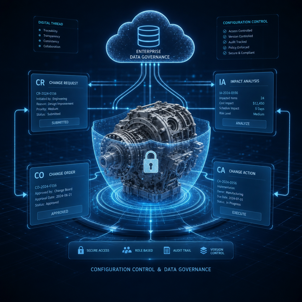
Within Dassault Systèmes’ 3DEXPERIENCE platform, this critical balance between engineering velocity and absolute control is achieved through a structured, multi-layered governance framework. This closed-loop configuration management ecosystem relies on four interconnected pillars: Change Requests (CR), Impact Assessments (IA), Change Orders (CO), and Change Actions (CA).
To build a high-performance configuration control board (CCB), you must look beyond the individual data schemas of these objects and master the overarching business process. This 2000-word guide breaks down the precise roles of these objects, explains how to execute an automated Impact Assessment, and establishes an enterprise-grade best-practice workflow for seamless engineering execution.
The Architecture of Change: Breaking Down the Pillars
A common pitfall for organizations adopting 3DEXPERIENCE is treating change objects as generic “approval tickets.” In reality, the platform’s change management engine decouples strategic evaluation from tactical execution. This is represented as a structured governance hierarchy:
    [ Change Request (CR) ]   <-- The "Why" and Potential Problem
               │
               ▼
   [ Impact Assessment (IA) ] <-- The "What If?" and Cross-Functional Scope
               │
               ▼
     [ Change Order (CO) ]    <-- The "Who," "When," and Executive Mandate
               │
               ▼
    [ Change Action (CA) ]    <-- The "How" and Real-Time CAD/BOM Execution
1. Change Request (CR) – The “Why” and “Proposed Intent”
The Change Request is the structural entry point for any change configuration loop. It is an abstract object that records a problem statement, a deficiency, or a potential opportunity for improvement. A CR can be initiated by any authenticated node in the enterprise ecosystem—not just CAD engineers. Quality analysts in the field, manufacturing planners on the shop floor, procurement managers tracking supplier obsolescence, or service technicians reading maintenance logs can all author a CR.
- Core Governance Function: Feasibility capture. It captures the intent to modify without granting permission to actually change any released data.
- Key Contents: References to issues or defect logs, text-based descriptions of the required enhancement, and references to target objects (e.g., an existing, locked Rev A physical product).
2. Impact Assessment (IA) – The “What If?” and Operational Analysis
An individual part or sub-assembly never exists in isolation. It is nested within multi-level Engineering Bills of Materials (eBOMs), attached to manufacturing routings (mBOMs), linked to finite element analysis (FEA) simulations, and bound to active supplier contracts.
The Impact Assessment is the critical investigative layer attached to the Change Request. It acts as a cross-functional checklist and data compilation utility to quantify exactly what will happen to the rest of the enterprise if the Change Request is approved.
- Core Governance Function: Risk mitigation and scope definition. It serves as an audit trail that answers: “What are the downstream consequences of this change across engineering, manufacturing, and supply chain domains?”
- Key Contents: Platform-driven where-used data, affected CAD documents, tool costing estimates, plant tooling rework checklists, and compliance validation requirements.
3. Change Order (CO) – The “Who,” “When,” and Business Authorization
When a Change Request passes its Impact Assessment and is approved by the reviewing authority, it hands governance off to a Change Order. The Change Order represents the commercial, financial, and executive management layer of the project. It handles scheduling, business unit sign-offs, and factory effectivity gates.
- Core Governance Function: Macro-level orchestration. It acts as the contract that dictates: “We have allocated budget and timelines to implement this change, and it must become effective starting at Serial Number X or Plant Y.”
- Key Contents: Change Control Board (CCB) lists, target release milestones, cost tracking metrics, cross-references back to multiple originating Change Requests, and child Change Actions.
4. Change Action (CA) – The “How” and Tangible Data Modification
The Change Action is the actual execution vehicle embedded inside the 3DSpace data vault. In a highly secure, controlled production environment, users cannot simply checkout a released part and modify it. All modifications, branchings, and status promotions must occur under the active context of a Change Action.
- Core Governance Function: Real-time auditable data transactions. It acts as the direct key that unlocks a business object for editing, tracking precisely who touched what line item down to the database attribute level.
- Key Contents: The CA utilizes two primary data grids:
- Impacted Items: The pre-change base objects (e.g., the existing Rev A assembly).
- Proposed Items: The design outputs generated by the task (e.g., the branched Rev B part, new geometry shapes, or substitute hardware items).
Deep Dive: Harnessing the Automated Impact Assessment
The true power of the 3DEXPERIENCE platform lies in its relational database structure. When a team conducts an Impact Assessment, they do not have to manually scroll through search windows to figure out what a modification affects. The system leverages its graph structure to perform digital Where-Used evaluations.
When a Change Request is evaluated, the configuration engineer triggers the platform’s native Impact Analysis tool. The system recursively crawls up and down the data tree, automatically populating the assessment grid with linked objects:
- Parent Assemblies (eBOM / mBOM): If you alter a small bracket, the Impact Assessment flags that the higher-level engine assembly structure is directly affected.
- Cross-Domain Specifications: The analysis identifies if the part is referenced by a 2D engineering drawing, a requirements management document, or an active test configuration case.
- Manufacturing Routing & Tooling: It traces connections into the manufacturing domain, warning if a specific injection mold or CNC fixture is linked to that object’s geometry.
Real-World Operational Metrics
During this phase, representatives from different operational groups populate their respective sections of the Impact Assessment:
- Manufacturing: “Altering this diameter requires re-machining the stamping die at Plant 1. Cost: $15,000. Retooling Lead Time: 3 weeks.”
- Procurement: “We currently hold 5,000 units of the legacy Rev A part in stock. We must scrap them or use them up before releasing the new revision.”
- Compliance: “This material substitution changes the weight of the aircraft component. We must submit a new declaration for FAA weight and balance certification.”
Best Practice Workflow: Process-Perspective Blueprint
To guarantee seamless coordination across teams, organizations should institutionalize a standardized, stage-gate change process. Below is the end-to-end best-practice workflow blueprint for executing an engineering change within the 3DEXPERIENCE ecosystem.
┌────────────────────────────────────────────────────────────────────────┐
│                      STAGE 1: CHANGE INITIATION                        │
├────────────────────────────────────────────────────────────────────────┤
│  1. Issue Discovery  ──►  2. Create Change Request  ──►  3. Link Data   │
└─────────────────────────────────────┬──────────────────────────────────┘
                                      ▼
┌────────────────────────────────────────────────────────────────────────┐
│                       STAGE 2: IMPACT ASSESSMENT                       │
├────────────────────────────────────────────────────────────────────────┤
│  4. Run Where-Used   ──►  5. Cross-Functional Input ──►  6. CCB Review │
└─────────────────────────────────────┬──────────────────────────────────┘
                                      ▼
┌────────────────────────────────────────────────────────────────────────┐
│                       STAGE 3: CHANGE AUTHORIZATION                    │
├────────────────────────────────────────────────────────────────────────┤
│  7. Generate CO      ──►  8. Set Effectivity        ──►  9. Delegate CAs│
└─────────────────────────────────────┬──────────────────────────────────┘
                                      ▼
┌────────────────────────────────────────────────────────────────────────┐
│                        STAGE 4: CHANGE EXECUTION                       │
├────────────────────────────────────────────────────────────────────────┤
│  10. Design Work     ──►  11. Validate Outputs      ──►  12. Promotion │
└─────────────────────────────────────┬──────────────────────────────────┘
                                      ▼
┌────────────────────────────────────────────────────────────────────────┐
│                        STAGE 5: CLOSE-LOOP AUDIT                       │
├────────────────────────────────────────────────────────────────────────┤
│  13. Release BOM     ──►  14. ERP/MES Sync          ──►  15. CO Closure│
└────────────────────────────────────────────────────────────────────────┘
Stage 1: Change Initiation (The Discovery Phase)
Issue Logging: A recurring validation failure or customer feedback report is logged inside the platform.
CR Generation: The Configuration Manager or Lead Engineer creates a formal Change Request (CR) object. They apply an enterprise tracking number, title, and clear description of the engineering change intent.
Data Association: The author attaches the existing production items requiring modification to the CR’s “Impacted Items” or “Context” tab. At this stage, all production items remain locked in their RELEASED lifecycle state.
Stage 2: Impact Assessment (The Evaluation Phase)
Automated Matrix Tracing: The configuration team activates the automated Impact Analysis utility. The platform maps out all parent structures, requirements, and downstream manufacturing processes that rely on the parts under evaluation.
Multi-Disciplinary Assessment Capture: The CR is routed sequentially or in parallel to engineering, quality, finance, and procurement stakeholders. Each team logs into the attached Impact Assessment (IA) view, completing their evaluation metrics regarding lead times, tooling reworks, inventory scraping costs, and certification compliance requirements.
Change Control Board (CCB) Gate: The complete package—the CR, the data metrics, and the cross-functional Impact Assessment—is presented to the CCB. The board reviews the total financial and scheduling impact. If approved, the CR is promoted to the APPROVED state. If rejected, it is set to CANCELLED, providing a documented audit history explaining why the change was dropped.
Stage 3: Change Authorization (The Project Strategy Phase)
Change Order (CO) Creation: Following CCB approval, a formal master Change Order (CO) is generated. The approved Change Request is structurally bound to this CO as an originating input.
Effectivity & Target Mapping: The Project Manager defines the target implementation constraints inside the CO window. They establish precise effectivity matrices (e.g., “This modification will go live at Manufacturing Plant 2 starting on August 15, 2026, corresponding to Assembly Line Chassis #10045 and forward”).
Change Action (CA) Delegation: The Project Manager breaks down the master Change Order into separate, bite-sized tactical task objects called Change Actions (CA). Each CA is given a dedicated technical owner (e.g., CA-1 to mechanical design, CA-2 to stress analysis, CA-3 to manufacturing tooling).
Stage 4: Change Execution (The Engineering Phase)
Design Under Context: The design engineer opens their 3DEXPERIENCE-connected CAD application (e.g., CATIA V5, CATIA 3DEXPERIENCE, or SOLIDWORKS) or the web-based Product Structure Editor. Crucially, before making any modifications, they select their assigned Change Action (CA) as the active “Work Under Context.”
BOM & Geometry Evolution: Working under this secure context, the engineer selects the parent revision assembly. The system allows them to create a new revision (e.g., evolving from Rev A to Rev B). The legacy Rev A is automatically populated into the CA’s Impacted Items grid, while the newly created Rev B is linked as a Proposed Item. The engineer updates geometries, replaces component definitions, and adjusts part specifications.
Peer Review & Pre-Commit Testing: When the design tasks are finalized, the engineer promotes the CA to the FROZEN state. This locks the design files, preventing further modifications while triggering automated business logic tests. These tests ensure that all Proposed Items match mandatory enterprise attribute constraints and are fully structured without broken database references.
Stage 5: Closed-Loop Audit & Release (The Verification Phase)
Change Action Approval: The Lead Reviewer evaluates the engineering outputs listed in the CA’s Proposed Items grid. Upon validation, they sign off on the CA, advancing it to the APPROVED state. This step automatically promotes the underlying CAD and eBOM data from FROZEN to RELEASED, unlocking the new revision for commercial application across the platform.
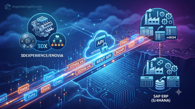
Downstream Integration Synchronization: The promotion of the child Change Actions emits an event message through the platform’s event-driven middleware. Integration components (such as a Teamcenter T4EA gateway or enterprise REST integrations) catch this transaction hook. The updated eBOM data, item master records, and manufacturing routing dataset are safely syndicated over to the corporate ERP and Manufacturing Execution Systems (MES) in real-time.
Master Change Order Closure: Once all child Change Actions (CAs) linked to the master Change Order (CO) have reached their approved state, the platform verifies that all deliverables are complete. The CO is formally closed, archiving the entire transaction history—from the initial Change Request and multi-department Impact Assessment down to the specific database modifications—into an unalterable compliance ledger.
Real-World Case Study: Implementing the Process
To observe how this workflow operates under tight manufacturing constraints, consider this real-world engineering scenario at an electric vehicle (EV) aerospace company:
The Problem (Stage 1)
During environmental testing of an urban air mobility drone, the battery cooling group discovers that a cooling line connector is leaking fluid under cold thermal cycles. A field service engineer submits a Change Request (CR-802) titled “Cooling Line Connector Fitting Optimization.” They tag the physical connector part (Part-2041, Rev A) as the target context item.
The Analysis (Stage 2)
The Configuration Team runs an automated where-used script on Part-2041. The platform indicates that this fitting is used inside two major assemblies: the main battery enclosure sub-assembly and the forward propulsion inverter cooling line. It also flags an active supplier contract with an overseas manufacturer.
The Impact Assessment is automatically routed to three departments:
- Aero-Thermal Design: They note that expanding the fitting diameter requires changing the mating port hole on the high-value battery enclosure wall.
- Tooling/Manufacturing: They report that the automated pick-and-place assembly robot at the factory requires a modified vacuum nozzle to grip the new fitting shape. Cost: $4,500.
- Procurement: They indicate that the factory currently holds 1,200 units of the legacy Rev A connector fitting in stock.
The CCB reviews the Impact Assessment. Because the fluid leak represents a safety flight risk, the board overrides the material scrap cost and approves CR-802.
The Management Authorization (Stage 3)
The system generates a Change Order (CO-550). The Project Manager targets implementation for the upcoming batch of prototype builds, configuring an effectivity constraint: “Effective starting at Hull Drone Serial Number #040 and forward.” They create two child Change Actions:
- CA-101 (Assigned to Mechanical CAD Team): Evolve the connector fitting geometry and modify the corresponding mating battery wall assembly port.
- CA-102 (Assigned to Manufacturing Engineering): Re-program the pick-and-place robot coordinates and order the updated vacuum nozzle component.
The Technical Work (Stage 4)
The CAD engineer opens CATIA 3DEXPERIENCE, launches the battery assembly model, and sets their active context to CA-101. They execute a “New Revision” command on the fitting. The platform creates Part-2041, Rev B, putting it into the IN_WORK lifecycle state, while tracking it under CA-101’s Proposed Items view. The old Rev A is marked as Impacted.
The engineer adjusts the outer flange diameter by 2mm to accommodate a thicker O-ring seal. They then open the parent battery enclosure model and update the hole diameter to match. Once finished, they promote CA-101 to FROZEN to initiate peer review.
The Release (Stage 5)
The Chief Engineer reviews the CAD cross-sections and structural analysis reports attached to the change action. Satisfied with the engineering integrity, they sign off on the task.
The approval of CA-101 automatically advances Part-2041 Rev B to the RELEASED state inside the 3DSpace repository. Simultaneously, the manufacturing engineer completes the robot adjustments under CA-102 and clicks approve.
The platform recognizes that all child operations under CO-550 are complete. The integration layer immediately pushes the new eBOM records and manufacturing bill details down to the factory’s ERP system. When the production line begins assembling Drone Serial #040, the work instructions dynamically load the Rev B fitting and display the updated robotic handling configuration, completely eliminating the risk of mismatched components on the assembly floor.
Conclusion
Implementing effective configuration management is not merely a matter of purchasing software licenses; it requires instituting a disciplined, logical sequence of governance rules. By decoupling intent from action through the targeted deployment of Change Requests, Impact Assessments, Change Orders, and Change Actions, the 3DEXPERIENCE platform gives enterprises a highly scalable control layout.
When you enforce the best-practice workflow—requiring comprehensive automated where-used tracking during Impact Assessments, binding modifications strictly to individual Change Actions, and locking product releases to strategic Change Orders—you protect your configuration baselines. You ensure your engineering teams retain the agility to iterate quickly while providing your organization with the precise structural oversight required to manufacture complex, safe, and cost-effective products.